In this part I'm going to look at why the pattern being generated for our long wrapped line looks like a chessboard.
Here's the program again:
1   X: add al,13h
2   int 10h
3   mov al,cl
4   xor al,ch
5   or ax,0CDBh
6   loop X
7   dec dx
8   jmp short X
This post focuses on the value of AL being calculated in lines 3-5. This register determines the colour of the pixels being written, and the pattern of these colours looks like a chessboard.
The logic can be summarised as:
AL = (CL XOR CH) OR 0xDB
In C-like notation:
AL = (CL ^ CH) | 0xDB
CX is being decremented in a loop. CL is the lower byte of CX and CH is the upper byte.
After this, when the program loops back to line 1, it adds 13h to AL and passes it to interrupt 10h. AH is always 0C, so this sets a pixel on screen at row DX, column CX, and colour AL.
I believe 13h is only being added because we're cramming the program into 16 bytes and at the very start of the program we needed it to be 13h to set the video mode to VGA.
Masking
5 or ax,0CDBh
Let's zoom in on line 5 - we'll get to the XOR in a moment.
What's this 0xDB constant?
In binary it looks like this:
1101 1011
OR-ing this constant with any 8-bit number x can only produce one of 4 possible results, depending on the values of the 3rd and 6th bits of x:
1101 1011   # 0xDB, 3rd and 6th bits of x are 0
1101 1111   # 0xDF, 3rd bit of x is 1, 6th bit is 0
1111 1011   # 0xFB, 3rd bit of x is 0, 6th bit is 1
1111 1111   # 0xFF, 3rd bit of x is 1, 6th bit is 1
This is a kind of bitmasking. I've previously commonly encountered masks being used with AND to set bits that weren't of interest to 0, usually so that particular bits could be queried. OR is being used in a similar way here to set bits that aren't useful to 1.
These values produce the four colours of our chessboard:
 0xDB
0xDB
 0xDF
0xDF
 0xFB
0xFB
 0xFF
0xFF
Subtract 13h (because of line 1) from the above constants to get the VGA palette indexes.
Which ranges of x produce which colours?
Let's look at numbers in which the 3rd bit is set.
| Binary | Decimal |
|---|---|
| 00100 | 4 |
| 00101 | 5 |
| 00110 | 6 |
| 00111 | 7 |
| 01100 | 12 |
| 01101 | 13 |
| 01110 | 14 |
| 01111 | 15 |
| 10100 | 20 |
| 10101 | 21 |
| 10110 | 22 |
| 10111 | 23 |
| 11100 | 28 |
| 11101 | 29 |
| 11110 | 30 |
| 11111 | 31 |
..etc
There's a clear on-off pattern with a period of 8. 4 numbers where it isn't set, then 4 numbers where it is, then off, then on etc.
For numbers where the 6th bit is set, there's a similar pattern with a period of 64.
This makes sense if you think about how digits flip as binary numbers increase. As the number increases, the first bit flips on and off every number representing odd or even. The second bit flips off for two numbers, then on for two numbers, and so on.
It helped me to think about how this also happens in decimal notation. As a number increases, the lowest digit cycles through 0-9, while the second digit changes every 10 numbers, the third every 100. So in binary notation, as a number increases, the nth bit cycles with a period of 2^n, and similarly in decimal, the nth digit cycles with a period of 10^n.
Here's the result of OR-ing 0xDB with the numbers 0-63, after which the pattern repeats itself.
| Range | Color | Bit 3 | Bit 6 |
|---|---|---|---|
| 0 - 3 | 0xDB | 0 | 0 |
| 4 - 7 | 0xDF | 1 | 0 |
| 8 - 11 | 0xDB | 0 | 0 |
| 12 - 15 | 0xDF | 1 | 0 |
| 16 - 19 | 0xDB | 0 | 0 |
| 20 - 23 | 0xDF | 1 | 0 |
| 24 - 27 | 0xDB | 0 | 0 |
| 28 - 31 | 0xDF | 1 | 0 |
| 32 - 35 | 0xFB | 0 | 1 |
| 36 - 39 | 0xFF | 1 | 1 |
| 40 - 43 | 0xFB | 0 | 1 |
| 44 - 47 | 0xFF | 1 | 1 |
| 48 - 51 | 0xFB | 0 | 1 |
| 52 - 55 | 0xFF | 1 | 1 |
| 56 - 59 | 0xFB | 0 | 1 |
| 60 - 63 | 0xFF | 1 | 1 |
What's this look like graphically?
Let's see what would happen if there was no XORing and we simply copied AL bitwise-OR 0xDB to CL - i.e. removed line 4 from the program:

As expected, the overall pattern repeats every 64 pixels. The colour changes every 4 pixels (from the third bit flipping on and off). Which two colours are flipping changes every 32 pixels (from the 6th bit flipping on and off).
Because 64 is a multiple of 320, the cycle is aligned with the row wrapping and so every line is the same.
Effect of XORing
The row being repeated in the screenshot above looks pretty good as a start, it's just that the successive rows need to be altered somehow to make the image look like a chessboard.
In order to convert the above pattern into the final chessboard, we need to apply some operation that
- Flips the order of the fast changing (every 4 pixels) colour sequence once every 4 rows to produce a mosaic tiling effect on the squares,
- Flips the order of the slow changing (every 32 pixels) colour sequence once every 32 rows or thereabouts to produce a checkered effect.
You guessed it - this is what the XOR instruction accomplishes.
As CX is decremented from 65535 down to 0, AL at each step is set to CL XOR CH. CH is the upper byte, which means it's decrementing every 256 iterations. Meanwhile, CL is decrementing every iteration from 255 to 0 in a cycle.
The XOR instruction is being used to flip bits. CH is used as a mask specifying which bits to flip in CL, so which bits are being flipped changes every 256 pixels.
Without the mask 0xDB, this is what it looks like - crazy chaos with some funky recurrent patterns! How is this useful?
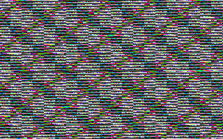
Well, the effect of applying the mask 0xDB is that only flips of the 3rd and 6th bits in AL have a visible effect, as the other bits are always set to 1 by the following OR instruction and their values are effectively ignored.
When the 3rd bit is being flipped, the order of the 2 colours in the faster 4 pixel cycle is swapped around - in other words, 0xDF comes first in the pattern instead of 0xDB.
When the 6th bit is being flipped, the 2 sets of colours in the 32 bit cycle are flipped - that is 0xFB and 0xFF come first instead of 0xDB and 0xDB.
So it seems like flipping these bits in the right sequence will be enough to produce the alternative patterns we need for our chessboard.
Sequencing
So what values of CX cause bits 3 and 6 to be 1 in CL, and therefore flipped before being written to AL? Or in other words, for what x values in the long wrapping row is the pattern going to change?
Well, this is where there's a catch.
As we saw in the earlier section on OR-ing, in a monotonic sequence the nth bit cycles with a period of 2^n.
So, when CX is being decremented in the loop, CH, being the highest 8 bits of the 16 bit number being decremented, cycles its 3rd bit (CX's 11 bit) with a period of 2^11 (2048).
This means that whether the 3rd bit of CL is being flipped before being copied to AL changes once every 1024 pixels.
But actually, 4 rows of pixels at 320x200 is 1280 pixels, so the change actually happens 256 pixels short - that's 8 squares! Fortunately, 1280 is divisible by 32, so the glitch occurs at the border of a square and isn't that visible.
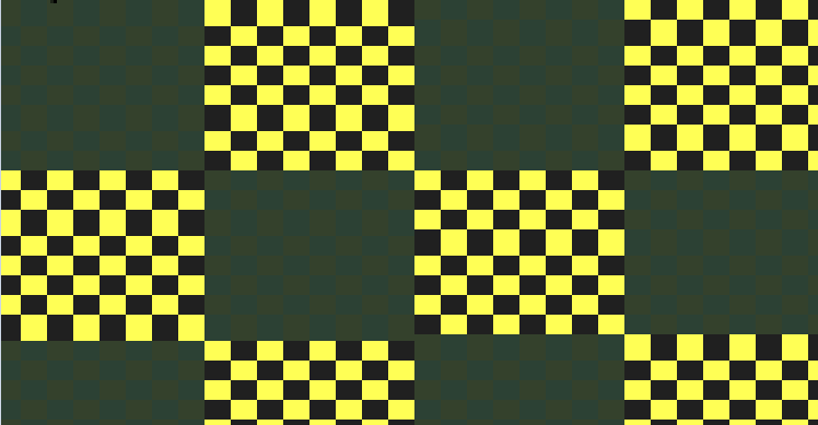
Take a look at this zoomed in top left corner when DX is zero. The first alternative row of boxes in the 2 top-left squares appear a pixel higher than the same row in the following squares. That's the glitch - after 1024 pixels (32 squares), the alternating pattern changes cycle, and there's 10 squares per row, so it changes after the second square in the row. You can also see the same glitches all over the graphic once you know to look, as it usually doesn't fall on the screen edge.
This glitch isn't noticeable if the chessboard is scrolling quickly, but at slow speeds it produces a weird squeezing and un-squeezing effect. If you didn't know better, you might just mistake it for typical animation tearing.
Meanwhile, CH cycle its sixth bit with a period of 2^14, so the slow-changing square pattern changes sequence every 8192 pixels. 8192 pixels is 25 rows of 320 pixels, plus another 192 pixels (or 6 squares). This misalignment produces another visible glitch:
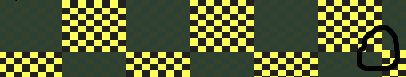
This is again the zoomed in top left corner when DX is zero, but here I've circled another glitch. The row has switched to an alternate square pattern after the 6th square - it's just not very visible overall!
I'd originally expected that the tile heights would be closer to 32 rows (as they are 32 columns wide), but the pixel aspect ratio of 320x200 is 16:10 (i.e. pixels are 1.6 higher than they are wide) so this makes sense if we want the tiles to look square.
Other masks
So, why this mask in particular? Why the 3rd and 6th bits?
No reason - this is just the mask the author chose. It produces a tiling pattern with appropriate light and dark colours. I poked around with a few other masks and it wasn't hard to find other chessboards - it's an 8 bit mask and so there's 255 possibilities.
Then I had the idea of iterating through the possible masks using DL as the mask, writing it to AL - i.e. decrement the mask every time we scroll. Here's the result:

If you enjoyed that half as much as I did, here's a 30fps version of it at 10x the speed for your viewing pleasure: kasparov-intense.gif. Zoom in for best results!
Still want more? Here's one in which as well as decrementing the mask, we subtract DX from CX in the inner loop, producing horizontal motion and an interesting shimmering effect due to diagonal tearing: kasparov-oceanic.gif. Cool! Not 16 bytes though.. :)
That's the conclusion to this series - if you got this far, congrats - I hope you had as much fun reading as I had working this all out!